DEVELOPMENT BOARDS / MODELS / SOFTWARE

Rapid prototyping.

Build, test and refine your idea.

Get a working demonstrator, repeatable build instructions and test findings that guide the next decision. We combine development boards, MATLAB / Simulink models, firmware and custom software to demonstrate and evaluate the agreed product functions.

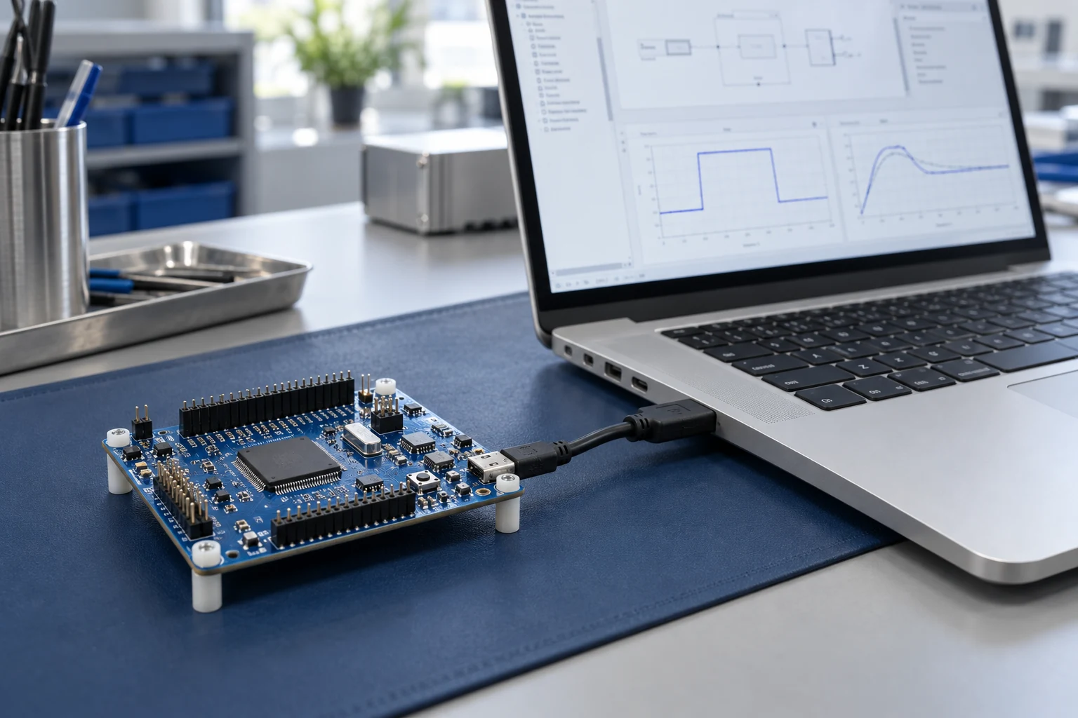
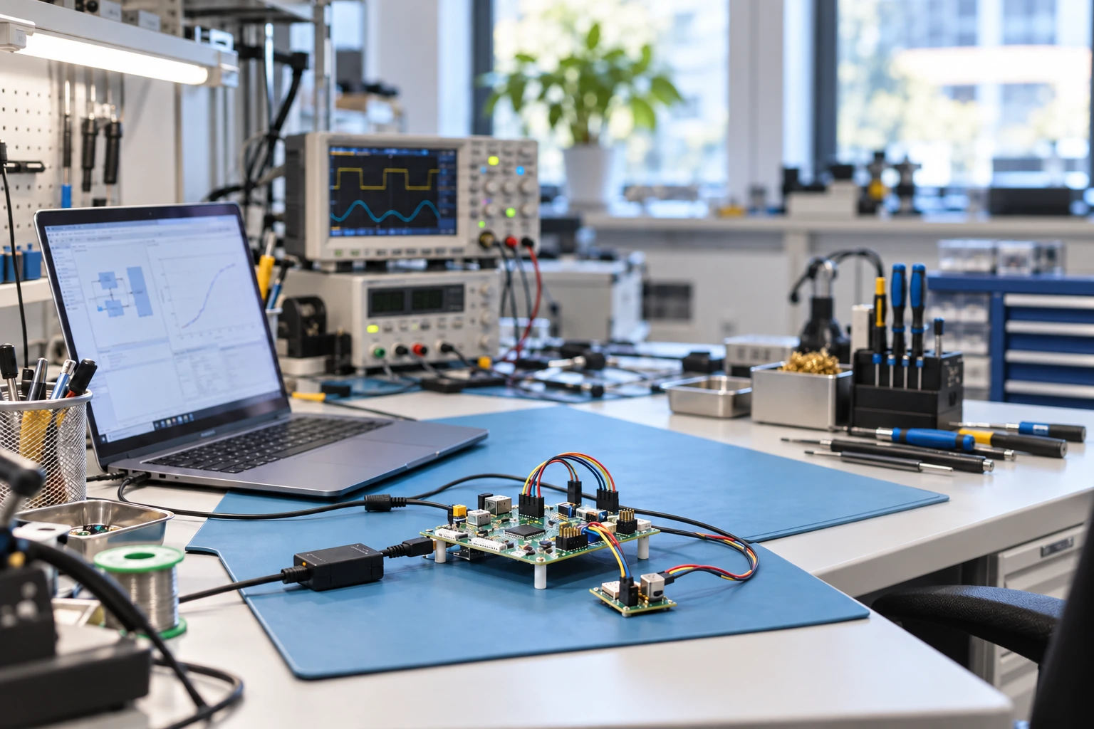
Illustrative rapid-prototyping workbench with a laptop, development boards and test instruments
FROM MODEL TO HARDWAREAlgorithms, electronics and software brought together on the bench.

WHAT WE DEVELOP

From development board
to working prototype.

Engage us for a complete demonstrator or a specific task, from getting a board running to developing its control software and operator interface.

Development boards & integration

Start with an evaluation board or ready-made module selected for your requirements. Connect sensors, actuators and communication interfaces to build a functional prototype.

  • Microcontroller platforms with MATLAB / Simulink integration
  • CAN, Ethernet, UART, RS-485, SPI and I²C
  • Interface adapters, wiring and prototype enclosures
MATLAB / Simulink modelling

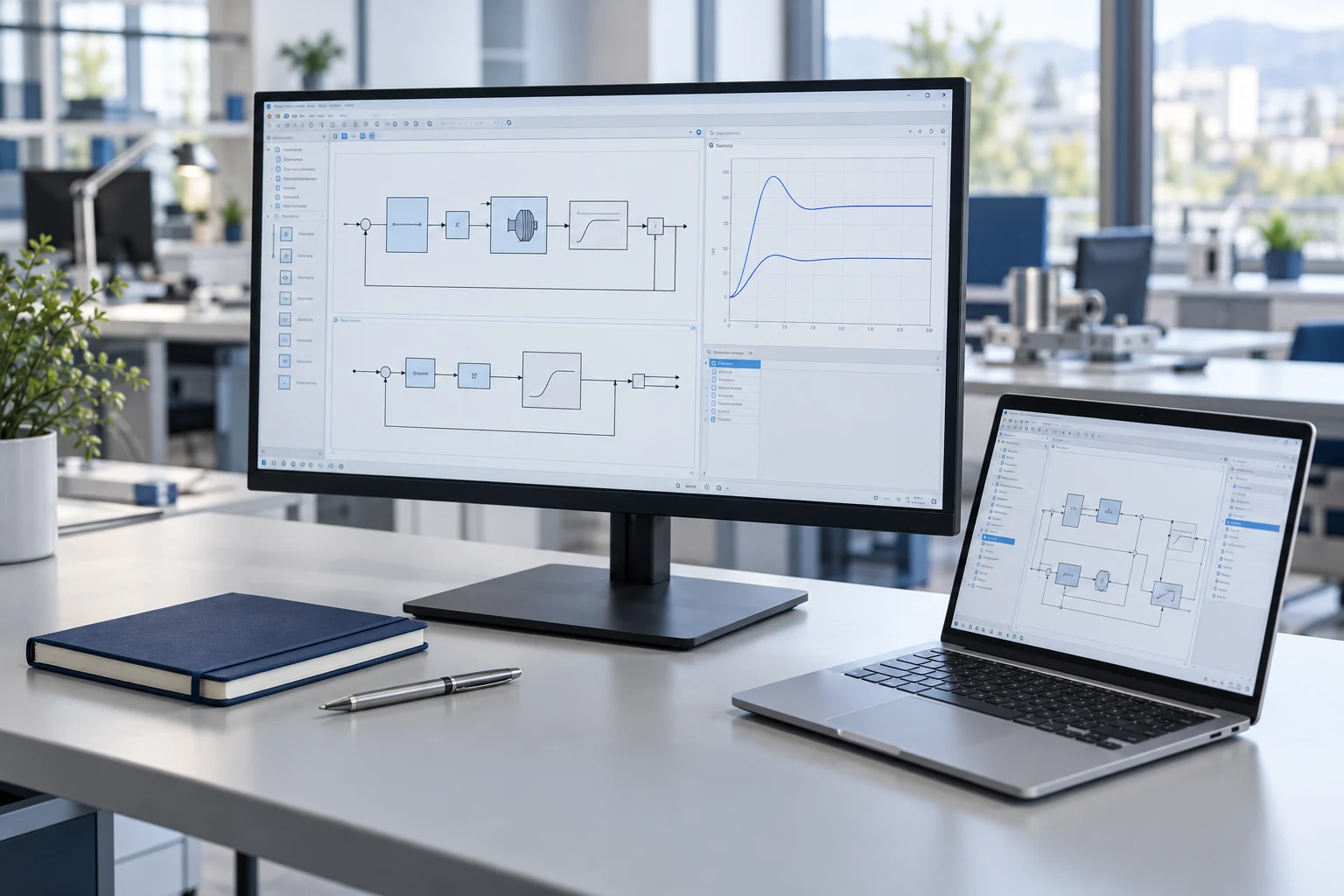
Develop control algorithms, signal processing and operating sequences in MATLAB, Simulink and Stateflow. Simulate expected behaviour before testing it on hardware.

  • Algorithm models, state machines and test scenarios
  • C / C++ code generation where supported
  • Comparison of model results with measurements

Embedded software & flashing

Build firmware, integrate device drivers and configure the target toolchain. Program the board, debug the application and check its behaviour on the bench.

  • Firmware builds and peripheral integration
  • SWD / JTAG, USB or supported bootloader flashing
  • Start-up, timing, communication and recovery checks

Custom software & test tools

Create the software needed to operate, configure and evaluate your prototype. Keep the interface clear so the team can understand the system and investigate issues.

  • PC applications, dashboards and human-machine interfaces
  • Configuration, diagnostics and data logging
  • Automated test tools and firmware update utilities

MATLAB / SIMULINK HARDWARE OPTIONS

Choose the right microcontroller.

These families offer integration through MathWorks support packages, dedicated blocksets or manufacturer tools. We select the platform around the interfaces, performance and software needs of your prototype.

Example microcontroller families and their MATLAB / Simulink integration
ManufacturerExample familiesIntegration route
STMicroelectronicsSTM32F4, STM32G4 and STM32H7Embedded Coder support package or STM32 Microcontroller Blockset, depending on the MATLAB release.
Texas InstrumentsC2000, including F280049C and F28379DC2000 Microcontroller Blockset for supported devices and peripherals.
NXPS32K1 and S32K3NXP Model-Based Design Toolbox for the selected device family.
InfineonAURIX TC3x and TC4xFamily-specific Embedded Coder support packages and the required compiler toolchain.
MicrochipdsPIC33, PIC32 and selected SAM devicesMPLAB Device Blocks for Simulink, with MPLAB X and the appropriate XC compiler.

Exact device, peripheral and software-version compatibility is checked for each project. Code generation, flashing and debugging are configured for the selected board, support packages and toolchain. Custom driver integration is included where required by the agreed scope.

AI INTEGRATION

AI for your
working prototype.

Add machine learning where it helps the prototype solve a defined problem. Applications include detecting unusual sensor behaviour, estimating values that are difficult to measure, and recognising patterns in images, sound or time-series data.

We connect the AI model to the prototype’s sensors, firmware and application software. The processing location is chosen to suit the workload and the project’s timing, power and connectivity requirements.

Agree on accuracy, response time and fallback behaviour before deployment. Validate the model with representative data and document its operating limits.

  1. Prepare representative data

    Review the available measurements, define labels and features, and keep independent data for evaluating the model.

  2. Develop and evaluate the model

    Use MATLAB machine learning and deep learning tools to compare approaches, measure prediction quality and investigate errors.

  3. Integrate and test on the target

    Deploy inference on suitable embedded hardware, an edge computer or a PC application. Measure accuracy, memory use and response time in the intended operating conditions.

THE V-MODEL

Clear requirements.
Measurable results.

We agree on what the prototype needs to do, turn those requirements into a design, and define the checks that will demonstrate the result. The level of detail is matched to the scope and risks of the project.

V-model: from requirements and design to implementation, verification and validationFollow the left branch from user needs to system requirements, architecture and detailed design. Build and flash the prototype at the bottom. Follow the right branch upwards through unit, integration and system verification to acceptance and validation. Dashed horizontal links connect each definition to its corresponding checks. Test planning begins with the requirements, and reviews and testing continue throughout development.DEFINE & DESIGNINTEGRATE & CHECKAcceptance criteriaUser needs & intended usePurpose, users and operating contextDefine what the prototype must showAcceptance & validationDemonstrate the agreed use casesConfirm suitability for the intended useSystem test criteriaSystem requirementsFunctions, performance and constraintsSet measurable limits and test conditionsSystem verificationEvaluate the complete prototypeCheck the agreed system requirementsInterface checksArchitecture & interfacesAllocate hardware and software functionsDefine connections and data exchangeIntegration verificationConnect boards, firmware and PC softwareCheck interfaces and combined behaviourUnit checksComponent & software designDesign algorithms, circuits and driversDefine component behaviour and limitsUnit & component verificationCheck individual functions and modulesRecord results against their specificationsBuild & flashImplement models, code and hardware.Program the selected development board.
Follow the V from definition to implementation, then through the checks. Dashed links connect each design stage to its test criteria.

Each design stage has a corresponding check.

  1. DEFINE & DESIGN

    User needs & intended use

    Purpose, users and operating context. Define what the prototype must show.

    MATCHING CHECK

    Acceptance & validation

    Demonstrate the agreed use cases. Confirm suitability for the intended use.

  2. DEFINE & DESIGN

    System requirements

    Functions, performance and constraints. Set measurable limits and test conditions.

    MATCHING CHECK

    System verification

    Evaluate the complete prototype. Check the agreed system requirements.

  3. DEFINE & DESIGN

    Architecture & interfaces

    Allocate hardware and software functions. Define connections and data exchange.

    MATCHING CHECK

    Integration verification

    Connect boards, firmware and PC software. Check interfaces and combined behaviour.

  4. DEFINE & DESIGN

    Component & software design

    Design algorithms, circuits and drivers. Define component behaviour and limits.

    MATCHING CHECK

    Unit & component verification

    Check individual functions and modules. Record results against their specifications.

Build & flash

Implement the models, code and hardware, then program the board. Begin with unit checks and progress through integration, system verification and acceptance.

VerificationCheck the prototype against the agreed technical requirements.

ValidationConfirm that it serves the intended users and use cases.

Plan the checks when defining the requirements. Review, simulate and test throughout development, then update the design and repeat the affected checks as the prototype evolves.

Make requirements clear

Capture the purpose, functions, interfaces and constraints. Resolve open questions, give each requirement a reference and agree on measurable acceptance criteria.

Connect design and evidence

Link requirements to the relevant models, hardware, software and test cases. Requirements Toolbox and Simulink Test can support this traceability within the agreed workflow.

Manage changes and results

Record the tested configuration, results and open issues. When a requirement changes, review the affected design and tests, repeat the relevant checks and update the handover.

MIL / SIL / PIL / HIL

Test the model.
Verify the implementation.

Choose the testing stages around your prototype, its risks and the available hardware. Each stage answers a different question as the design moves from simulation to an embedded implementation.

Illustrative computer workstation showing control models and simulated responses, without a physical controller

MIL

Model-in-the-loop

Simulate the controller and the physical system together in MATLAB / Simulink. Check algorithms, operating modes and expected responses before deploying code to hardware.

Controller
Controller model on the computer
Test environment
Simulated physical system

What this checksCheck the control logic against the requirements.

Illustrative software workstation showing a code editor and test comparison results on two monitors

SIL

Software-in-the-loop

Run generated C or C++ code on the development computer. Compare its results with the model using the same test inputs and agreed tolerances.

Controller
Compiled code on the computer
Test environment
Simulated physical system

What this checksCheck that the generated code matches the model.

Illustrative microcontroller development board connected to a laptop for processor-in-the-loop testing

PIL

Processor-in-the-loop

Compile code for the selected microcontroller and run it on that processor. Compare outputs with the model and assess execution time where supported.

Controller
Compiled code on the target processor
Test environment
Computer simulation exchanging test data

What this checksCheck the implementation on the intended processor.

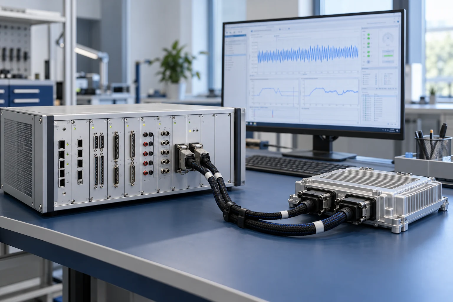
Illustrative embedded controller connected through a wiring harness to an industrial real-time simulator

HIL

Hardware-in-the-loop

Connect the real controller to a real-time simulation of the physical system. Check I/O, communications, timing and responses to simulated faults.

Controller
Firmware on the real controller hardware
Test environment
Real-time simulator connected through I/O

What this checksCheck hardware and software working together.

One set of requirements. Comparable results.

Reuse test scenarios where practical and record the model version, code build, target configuration and results. Simulink Test and Requirements Toolbox can connect the tests to the agreed requirements; Embedded Coder supports suitable SIL and PIL workflows.

The right setup for each stage.

SIL and PIL exchange simulation data without requiring real-time execution. HIL needs a suitable real-time plant model, simulator hardware and I/O. A Simulink Real-Time setup and its hardware requirements are agreed for each project.

AI-generated illustrations of typical test setups. Equipment and software are selected for each project.

BUILD / MEASURE / REFINE

Put the design to work.
See how it performs.

A useful prototype connects the model, the code and the physical hardware. We make the build repeatable and the results easy to review.

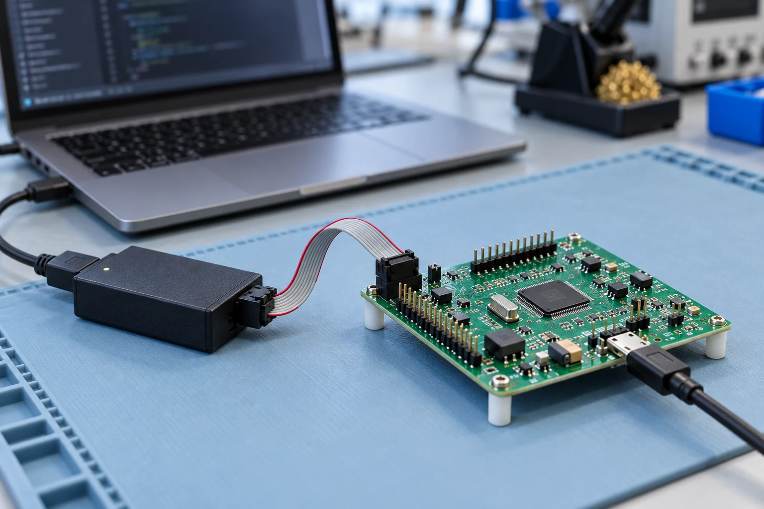
Illustrative development board and USB debugger with both ribbon-cable connectors visible beside a programming laptop

FIRMWARE & CUSTOM SOFTWARE

From code to a running board.

Compile the firmware, program the target and debug its start-up, drivers and communications. Build custom PC tools to configure the prototype, display live values, log data and support firmware updates.

What you receiveAgreed source files, a repeatable build and flashing procedure, and clear operating instructions.

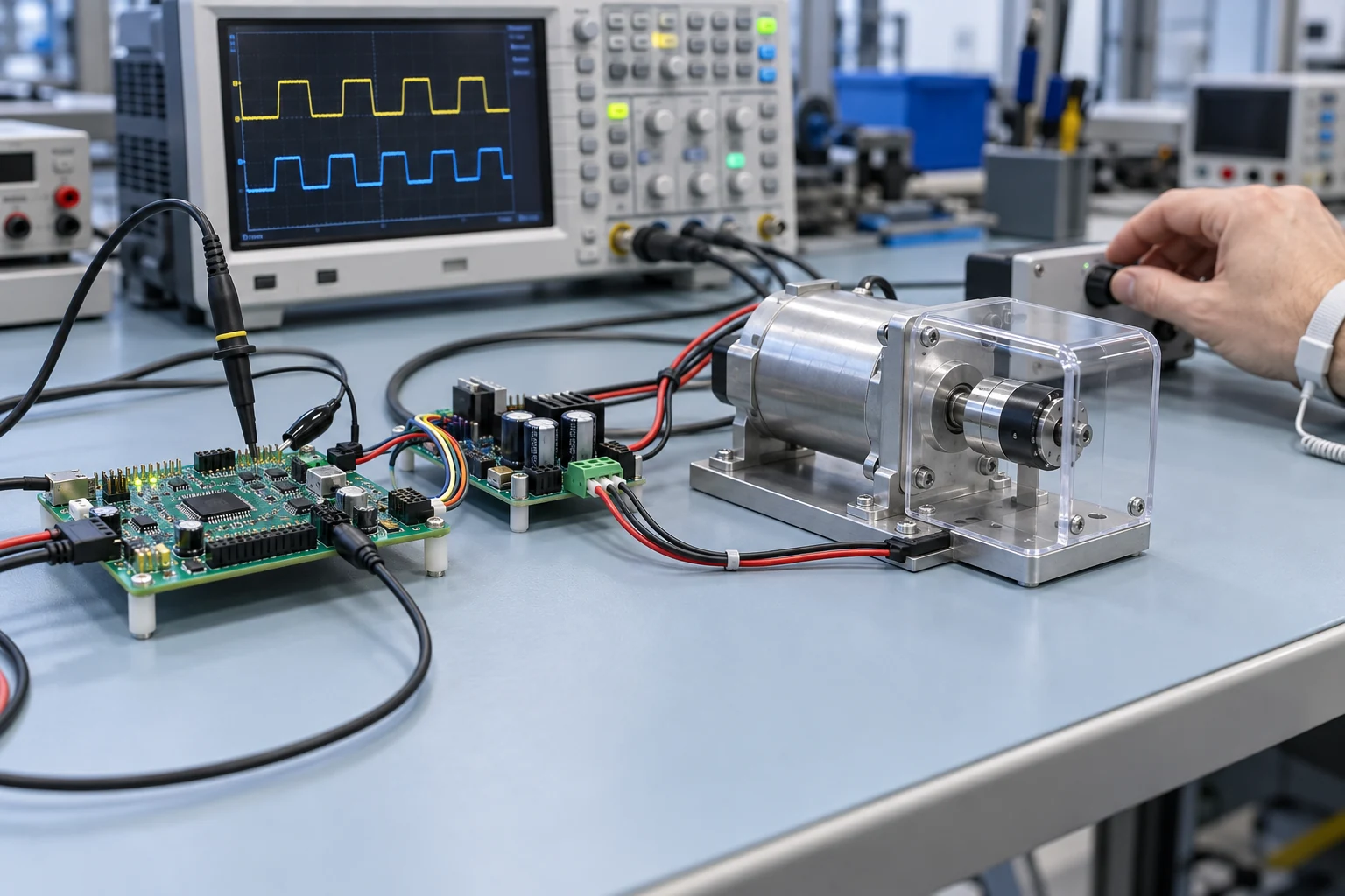
Illustrative motor control test bench with a development board, driver electronics, guarded motor and oscilloscope

BENCH TESTING & MEASUREMENT

From expected to measured behaviour.

Check sensor readings, control response, timing and fault handling. Compare measurements with the model and acceptance criteria, investigate differences, refine the design and repeat the relevant tests.

What you receiveRecorded test results, the tested configuration, known limitations and recommendations for further development.

AI-generated illustrations of typical engineering activities. Hardware, tools and test arrangements are selected for each project.

THE TECHNICAL HANDOVER

What you receive.

The quotation defines the hardware, software and documentation included in the delivery.

  • Functional prototype with the agreed development boards and interfaces
  • Agreed MATLAB / Simulink models, firmware and custom software source files
  • Build, flashing, configuration and operating instructions
  • Test results, known limitations and recommendations for further development

When the prototype has answered the initial questions, continue with hardware design or mechanical design for the next development stage.

START YOUR PROTOTYPE

Turn an idea into
a working prototype.

Tell us the intended functions, interfaces, preferred board or existing hardware, and target date. Mention any models, code or measurements already available.

Discuss your prototype

Scope, deliverables and pricing are confirmed in a quotation.

Back to all services